Flasher 5 PRO - Universal Programming Tool for Renesas Series Microcontrollers
Programming tool for Renesas M16C/62, M16C/80, M32C, M79, R32C, R8C series of microcontrollers. This tool allows the in-circuit programming of internal MCU flash via the serial synchronous or asynchronous interface.
- Small, compact housing
- Easy to use windows program
- Serial (in target) programming supported
- Programming / Verifying / Read back supported
- 64MByte internal Flash memory to store target program
- High speed programming: app. 17 sec for 256 KB in serial mode with 10 MHz M16C target for programming and verification
Superceded by Flasher Pro
The Flasher 5 Pro has been superceded by the introduction and expansion of the Flasher Pro. All relevant devices traditionally supported by the Flasher 5 series are now supported by Flasher Pro. Switching to Flasher Pro opens access to a wider range of supported devices, a much faster hardware platform and a future-proof concept for production programming.
- 1.Using The FLASHER PC Program
- 2.Operating Flasher in Stand-Alone Mode
- 2.1.Setup
- 2.2.Additional Options
- 2.3.ID Check
- 3.Remote Control of FLASHER 5 PRO
- 4.ASCII Command Interface
- 5.Using the Serial Link to Program in Circuit
- 6.Serial Programming, Technical Details
- 7.Flasher 5 PRO Specifications
- 8.10-pin Needle Adapter
- 9.Supported Devices
- 10.Package Content
Performance of MCUs with Internal Flash Memory
The following table lists program and erase performance values for different controllers.
| Microcontroller | Memory Size (KByte) | Blank check (Sec) | Erase time (Sec) | Program (Sec) | Program & Verify (Sec) | Verify (Sec) |
|---|---|---|---|---|---|---|
| R8C/1B4 R5F211B4SP | 18 | 1.9 | 2.1 | 3.9 | 4.7 | 1.8 |
| R8C/L38C R5F2L38CCNFP | 132 | 2.8 | 3.2 | 13.1 | 17.9 | 5.9 |
| M32C/87 M30879FLGP | 1024 | 11.6 | 11.4 | 29.1 | 42.1 | 13.5 |
Getting Started
The Flasher PC software be downloaded from the Flasher Download page. Starting the setup program will guide you through the installation process.
Connecting FLASHER to the PC
- Connect FLASHER to a PC running Windows using the RS232 cable and run the FLASHER software FLASHER.EXE.
- Connect FLASHER to the power supply.
- Set up the device via Options menu of PC program.
- For in-circuit programming: Connect FLASHER to the target system via the 10 pin interface cable.
- Before connecting the target system to Flasher, ensure, there is no ground potential difference between target and Flasher, otherwise the Flasher may be damaged.
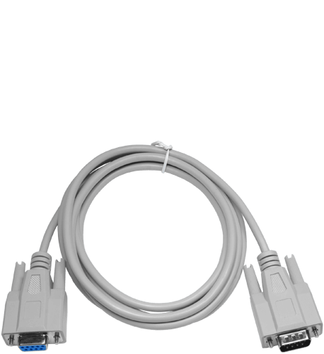
A standard serial interface cable (null modem) can be used to connect FLASHER to the PC. The pin assignment of the 9 pin SUB-D male RS-232 interface connector is as follows:
| Pin | Signal | Function | Host Signal |
|---|---|---|---|
| 2 | RxD | Serial asynchronous (RS232) data input | Serial data output (TxD) |
| 3 | TxD | Serial asynchronous (RS232) data output | Serial data input (RxD) |
| 5 | GND | Signal ground | Signal ground |
Using The FLASHER PC Program
Flasher comes with an easy to use Windows program. It allows reading of program files in Motorola or Intel hex format. The following is a screen shot of the FLASHER.EXE with loaded target program.
Communication between PC and FLASHER
Make sure the power supply is connected (one of FLASHERs LEDs should be illuminated) and FLASHER is connected to your PC with a 1:1 RS232 cable as supplied. If the PC-program displays anything other than "No communication" under flasher status, the communication between Flasher and your PC is functioning.

First Time Setup of FLASHER
When using FLASHER for the first time, please select the menu point Options->Device. You will see the following dialog box:
The device properties dialog allows selection of the chip area you would like to access, the sectors of the on chip-flash and the interface you would like to use. The serial interface requires a cable to connect FLASHER to your target. For targets running at low frequencies, it may be necessary to set the speed option to Slow. To select an other device, press the „Select Device“ button. The device selection dialog will open. You can select the group in a dropdown list and the specific device from the list below.
Now you should be able to blank check, clear, program, verify or read the target chip in serial mode (if your target is properly connected to the FLASHER). The first time you program or verify, the PC downloads your your target program to the FLASHER, where it is stored in the on board FLASH chip for programming or verification. The PC-Program stores all setup information in the registry; when you start the program the next time, it will start with the same settings.

Programming / Clearing / Verifying / Blank check
Select one of the commands in the TARGET menu to start the operation. Note that some of the menu points may be grayed if you have no connection to the target or no file loaded

Operating Flasher in Stand-Alone Mode
After downloading, the target program and all settings are stored in FLASHERs on board FLASH memory and remain valid until new settings or data are sent to FLASHER. Any number of microcontrollers may now be programmed by FLASHER (one at a time) without the need of a host PC, by simply pressing the start button. FLASHER will use the settings which have been made in the PC-program. This includes the selection of the target address range as well as any options. Whether the target CPU will be erased before programming depends on setting of option "Automatic clear before program". Progress and result of the operation is indicated by FLASHERs LEDs:
| Status of LED | Meaning |
|---|---|
| GREEN, flashing | Erasing / Programming / Verifying in progress |
| GREEN | Programming operation successful |
| RED | rogramming operation failed |
Setup
The operating mode of FLASHER may be changed using the setup dialog from the Options menu.Power up mode, Power down mode and Reset mode should not be changed for normal operation. Setting of Power down mode has no effect on FLASHER MV3.You may change the reset active and reset inactive time, if required by your target hardware. All setup settings are stored permanently in FLASHER after pressing 'Save setup' button.

Additional Options
Additional options The Filling & Misc. Options from the Options menu may be altered if required. Normally there is no need to change any of these settings. Improper setting of the fill byte may lock your target CPU! When programming blank (virgin) CPUs, Automatic clear before program is not required, so this feature can be disabled to speed up programming procedure. Detailed errorlevel on return option may be used to return a detailed errorlevel to the calling program when Flasher is used in batchmode.

ID Check
When programming the chip in serial mode (in target), an identification code of 7 or more bytes has to be supplied. If the target MCUs user program area is blank, this ID-value does not matter. However, after programming, these values need to be set correctly, because otherwise FLASHER will be unable to communicate with the target CPU. These ID-values can be set using the menu point Options|Pass code (7 or more byte ID). With a standard program, these values should be 0, as the high bytes of the interrupt vectors which are used to store the values are usually 0. For more detailed information, please consult the Renesas users manual. The menu point "Edit|Copy Renesas Id into loaded file" can be used to set these ID bytes.

Problems with ID check
You should act carefully when using the ID bytes. If you do not know the ID-value programmed into a target chip, there is no way to erase, read or reprogram the chip in-circuit for most of the CPUs. Some CPUs offer a special ID-byte combination which forces a complete chip erase. We recommend not to use ID bytes during the development process.
Remote Control of FLASHER 5 PRO
FLASHER 5 PRO can be remote controlled by automated testers without the need of a connection to a PC and Flashers PC program. Therefore FLASHER 5 PRO is equipped with additional hardware control functions, which are connected to the SUBD9 female connector, normally used as RS232 interface to a PC. The following diagram shows the internal remote control circuitry of FLASHER:
ASCII Command Interface
FLASHER with firmware version 1.84 or above can be controlled without the need of Flashers PC program. The FLASHER firmware contains an ASCII command interface function. Any application may send commands via RS232 to the Flasher to start programming / verifying / blank checking of the target CPU.
A manual which describes the ASCII command interface can be downloaded from our download page.
Using the Serial Link to Program in Circuit
FLASHER can be used for in circuit programming of supported CPUs, which incorporate built in firmware for serial update of user flash. The target system has to be designed to support this mode of operation. Refer to target specific connection diagrams or Users manuals of your target CPU.
Serial Programming, Technical Details
Serial programming uses a clock synchronous interface for most of the supported CPUs. 8 bits of data (1 byte) is transferred at a time. The commands which are used are described in the Renesas manual. In general, the sequence is as follows:
- FLASHER resets the target system by pulling the /Reset line low for a short period of time (user selectable reset active time)
- FLASHER waits for the user selectable reset inactive time (tRD) in order to allow the target system to recover from reset
- FLASHER checks the BUSY line. If it is active (high level)
- FLASHER stops with error message 40: Target chip says "BUSY" because it can not communicate with the target system
- FLASHER outputs one clock (clock changes from high to low and back). BUSY should now be active (high) If it is not active, FLASHER stops with error message 41: Target chip: BUSY does not react
- FLASHER outputs 7 more data bits ( 7 clock cycles) and wait for BUSY to go low More data bytes are output (or read).
Flasher 5 PRO Specifications
The clocked synchronous interface from FLASHER to target system has to be connected to the 10 pin dual in line pin connector, (pin 1 is on the top left, marked at the connector) as shown in the diagram.
| Pin | Signal | Function | Specification / Remarks |
|---|---|---|---|
| 1 | VCCS | Positive supply voltage of target | Input 3.0 .. 5.5V to supply the interface |
| 2 | BUSY | Target CPU Busy signal output. | FLASHER Input with Pull-Up to internal 3.3V |
| 3 | SCLK | Target CPU Serial clock (input) | FLASHER Output, CMOS driver via 220 Ohms |
| 4 | RxD | Target CPU Serial data input | FLASHER Output, CMOS driver via 220 Ohms |
| 5 | CE | Chip enable signal of target CPU | FLASHER Input/Output |
| 6 | EPM | EPM signal of target CPU | FLASHER Input/Output |
| 7 | GND | Common signal ground | --- |
| 8 | RESET | RESET signal of target system | FLASHER Output, CMOS driver via 220 Ohms |
| 9 | CNVss | Target CPU CNVss signal | FLASHER analog Output |
| 10 | TxD | Target CPU Serial data output | FLASHER Input/Output |
The pull-up resistors of outputs are connected to VCCS. If RESET of the target system is driven by a reset circuitry with active high driver, RESET output of FLASHER must not be connected directly to CPU reset of target. For M16C/62 or M16C/80 targets you do not have to connect RESET to FLASHER; you can always manually reset your target system after connecting FLASHER.
Target system interface for M16C/62, M16C/80, M32C

Target system interface for M16C26, M16C28

Target system interface for M16C26A, M16C29

Target system interface for M37906F8

Target system interface for R8C groups

The Following Table Lists All Major Modifications of Flasher Software
| Version | New features | Improvements / Corrections | Flasher type |
|---|---|---|---|
| V2.15 | Added support for hardware revision 1.3 | NONE | Flasher 5 PRO |
| V2.14 | NONE | Under special circumstances the firmware update failed. Fixed. | Flasher 5 PRO |
| V2.12a | Range of selectable serial ports increased. | A serial com port in the range 1-256 can be selected in the Flasher software. | Flasher 5R3 / 5 PRO |
| V2.12 | NONE | Under special circumstances the Flasher lost the internal data after a power cycle. Fixed. | Flasher 5 PRO |
| V2.10 | Support for USB added. Support for Ethernet added. | The Flasher software can now communicate with the Flasher 5 PRO via USB or Ethernet. On USB the Flasher 5 PRO is identified via serial number. On Ethernet the Flasher 5 PRO can be identified either via IP address or serial number. | Flasher 5 PRO |
| V2.00s | Webserver added. Telnet server added. | Flasher 5 PRO now comes with a webserver. A telnet server is included which allows controlling the Flasher via Ethernet. The telnet server processes the same commands as used with ASCII mode over UART. Initially, Flasher 5 PRO connects to the Ethernet using DHCP. The tool 5PRO_UDPDiscover can be used to examine the IP address. The webserver may then be used to assign a fixed IP address. | Flasher 5 PRO |
| V2.00s | R8C/34W series supported R8C/34X series supported R8C/34Y series supported R8C/34Z series supported R8C/35D series supported M16C/63 series, additional devices supported | NONE. | Flasher 5R3 / 5 PRO |
| V2.00q | NONE. | Firmware update modified for Flasher 5 PRO. The previous version did not allow downgrading to an older version. Downloading and starting the new firmware V2.00q modifies the bootloader of Flasher 5 PRO which then allows downgrading the firmware. | Flasher 5 PRO |
| V2.00p | Asynchronous serial support for M16C/M32C/R32C with Flasher 5 PRO. | Programming speed improved for R8C. Problem with low baud rates for R8C/3x and R8C/Lx devices fixed. Could not be used in previuos versions of the firmware. Blank check time improved for R8C/3x and R8C/Lx devices. PC software 2.00p and a firmware update to version 2.00p is required to use the improvements. | Flasher 5 PRO |
| V2.00o | R32C series supported with Flasher 5 PRO. | NONE. | Flasher 5 PRO |
| V2.00n | M7900 series supported with Flasher 5 PRO. | Target reset driver firmware corrected. The push-pull output did not work in previous version. The reset output was driven in open drain configuration always, regardless the setup options. | Flasher 5 PRO |
| V2.00m | R8C/2K supported. R8C/2L supported. | NONE. | Flasher 5R3 / 5 PRO |
10-pin Needle Adapter
SEGGER offers the 10-pin Needle Adapter, which has been designed to connect Flasher 5, Flasher 5 PRO, Flasher ST7 or Flasher STM8 to a PCB which does not come with a mating connector or programming header. The designed pattern with 3 locating pins ensures that the adapter can only be connected in one way.
The 10-pin needle adapter allows manufacturers to save costs and space on their PCBs since there is no need to provide the PCB with additional connectors. It adapts from the 10-pin, 0.1 inch connector to a 10-pin, 0.05 inch needle pattern.
Supported Devices
Flasher 5 Pro supports M16C/62, M16C/80, M32C, M79, R32C, R8C series of microcontrollers.
Package Content
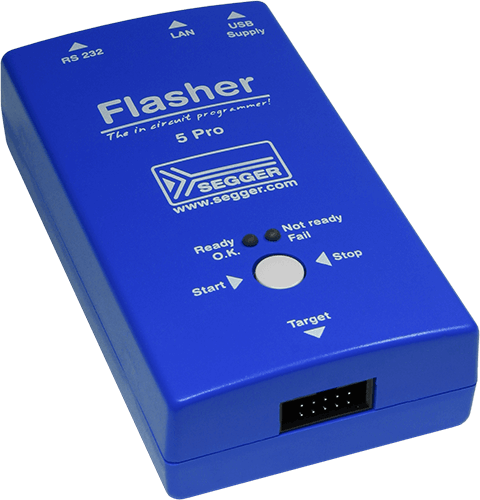
Flasher 5 PRO
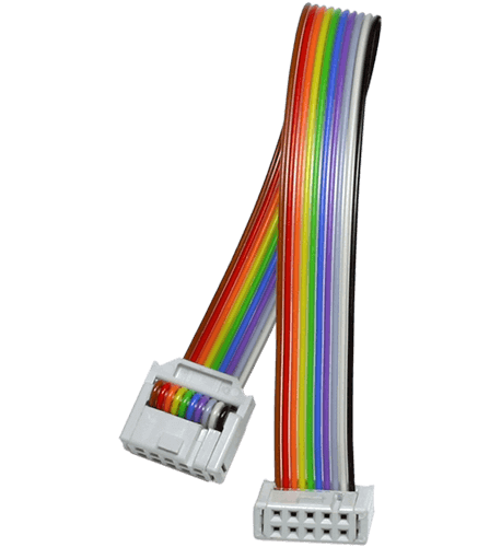
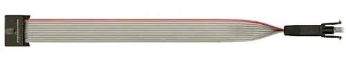
IDC target interface cable
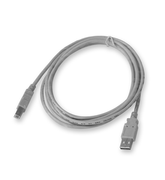
USB cable